| | |
|
| |
| | |
|


|
Graphtec GL7000 Data Acquisition
|
Item Number: GL7000
Manufacturer: Graphtec Corp
Part Number: GL7000
Product Options
* denotes required field
Graphtec GL7000 Display Option*
You must select an option for 'Graphtec GL7000 Display Option'.
Graphtec GL7000 SSD Option*
You must select an option for 'Graphtec GL7000 SSD Option'.
Graphtec GL7000 Module Selection 1*
You must select an option for 'Graphtec GL7000 Module Selection 1'.
Graphtec GL7000 Module Selection 2*
You must select an option for 'Graphtec GL7000 Module Selection 2'.
Graphtec GL7000 Module Selection 3*
You must select an option for 'Graphtec GL7000 Module Selection 3'.
Graphtec GL7000 Module Selection 4*
You must select an option for 'Graphtec GL7000 Module Selection 4'.
Graphtec GL7000 Module Selection 5*
You must select an option for 'Graphtec GL7000 Module Selection 5'.
Graphtec GL7000 Module Selection 6*
You must select an option for 'Graphtec GL7000 Module Selection 6'.
Graphtec GL7000 Module Selection 7*
You must select an option for 'Graphtec GL7000 Module Selection 7'.
Graphtec GL7000 Module Selection 8*
You must select an option for 'Graphtec GL7000 Module Selection 8'.
Graphtec GL7000 Module Selection 9*
You must select an option for 'Graphtec GL7000 Module Selection 9'.
Graphtec GL7000 Module Selection 10*
You must select an option for 'Graphtec GL7000 Module Selection 10'.
Accessory Options
* Whole number only
|

 Graphtec GL7000 Data Acquisition Graphtec GL7000 Data Acquisition |
|
Graphtec GL7000 Data Acquisition
The next generation Data Acquisition unit to measure the selected signal on demand with the selected number of channels and time interval.
Features
- Modular system allows expansion of measurements and channels
- Suitable for a variety of measurements by different type of amplifier module
- Multiple storages for reliable long term measurement
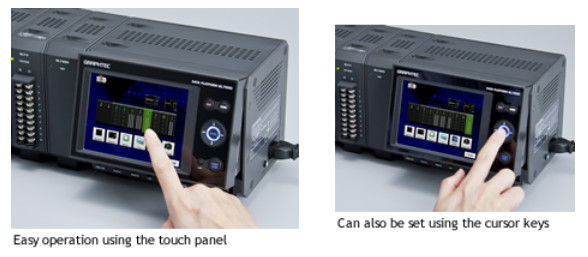
- Easy operation with large display and touch panel
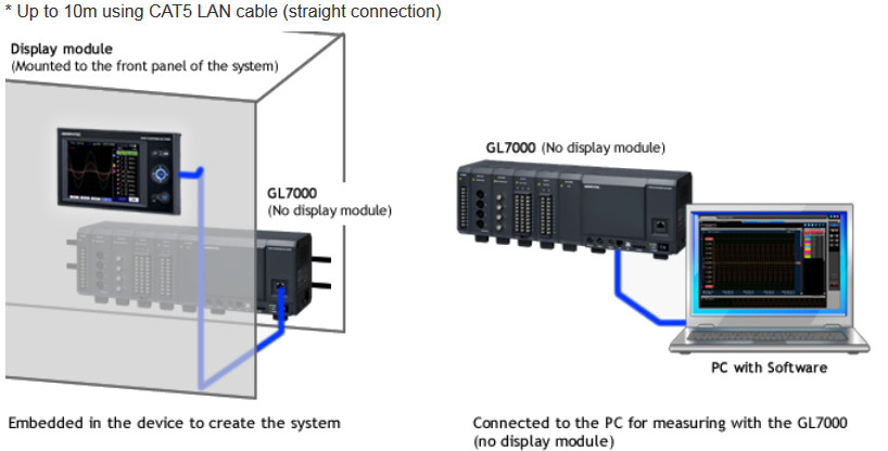
- Support stand-alone operation and embedding into a system
- High performance application software
Sampling speed
| Amplifier Module | Channels in 1 module | Max. sampling speed in the module | Media type to save data | Max. sampling speed in the GL7000 |
|---|
| Attached to 1 or 2 modules | Attached to3 or 4 modules | Attached to 5 to 10 modules |
|---|
Voltage Module
(GL7-V) | 10 channels | 1 k Samples/s
(1ms interval) | Built-in RAM |
1 k Samples/s
(1ms interval) |
|---|
| Built-in Flash |
|---|
| SD card |
|---|
| SSD *3 |
|---|
Volt./Temp. Module
(GL7-M) | 10 channels | 100 Samples/s
(10ms interval) | Built-in RAM |
100 Samples/s
(10ms interval) |
|---|
| Built-in Flash |
|---|
| SD card |
|---|
| SSD *3 |
|---|
High-speed voltage Module
(GL7-HSV) | 4 channels | 1 M Samples/s
(1μs interval) | Built-in RAM |
1 M Samples/s
(1μs interval) |
|---|
| Built-in Flash |
1 k Samples/s
(1ms interval) |
|---|
| SD card |
|---|
| SSD *3 |
1 M S/s
(1μs interval) |
500 k S/s
(2μs interval) |
200 k S/s
(5μs interval) |
|---|
Logic/Pulse Module
(GL-L/P) | 16 channels | In Logic mode,1 M Samples/s
(1μs interval) | Built-in RAM |
1 M Samples/s
(1μs interval) *1 |
|---|
| Built-in Flash |
1 k Samples/s
(1ms interval) *1 |
|---|
| SD card |
|---|
| SSD *3 |
1 M S/s
(1μs interval) |
500 k S/s
(2μs interval) |
200k S/s
(5μs interval) *1 |
|---|
In Pulse mode,10 k Samples/s
(100μs interval) | Built-in RAM |
1 M S/s
(1μs interval) |
Not Available *2 |
|---|
| Built-in Flash |
1 k S/s
(1ms interval) |
|---|
| SD card |
|---|
| SSD *3 |
1 M S/s
(1μs interval) |
|---|
- *1: Using in Logic mode, the module can be attached up to 7 units.
*2: Using in Pulse mode, module can be attached up to 2 units.
*3: SSD module is an option. Number of channels for pulse input will be limited when the High-speed voltage module and Logic/Pulse module are used simultaneously.
  Applications Applications
Software for high performance and easy operation
The GL7000 can be controlled by the GL-Connection software that is included. The software has convenient functions such as saving data to the PC, replaying captured data, and converting data form. It is an integrated application software for the GL series, the GL900, GL820 and GL220 can also be connected.*
* The version for supporting other GL series will be available in December 2012.
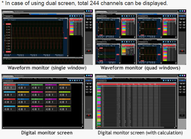
Various measurement screens
The measurement signal can be displayed as various types of screens by the unit, the module or the specific channels that are specified in the group function. It can also be displayed as a combination of the capturing data and captured data, the Y-T format and the X-Y format, simultaneously. Up to 112 channels can be displayed in each window.*
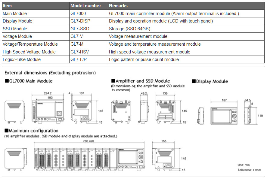
Dimensions
Technical Specifications
GL7000 main unit specifications
|
Item
|
Description
|
|---|
|
Number of module
|
Attached to up to 10 modules *1
|
|
Number of input channels
|
Max. 112 channels in one GL7000
|
|
External Input/Output signals *2
|
Input
|
Start/Stop, Trigger, External sampling, Auto balance
Signal type: Contact (relay), Open collector, Voltage
|
|
Output
|
Trigger, Busy, Alarm (10 channels) *3
Signal type: Open collector (pulled-up by resistor 10 k ohms)
|
|
Trigger, Alarm function
|
Trigger repeat
|
Enabled (ON): Automatically rearm for the next data capture
Disabled (OFF): Data capture is completed in a single trigger
|
|
Trigger action
|
Start or stop capturing data by the trigger
|
|
Trigger condition
|
Start: Off, Measured signal, Alarm, External, Clock, Week or Time
Stop: Off, Measured signal, Alarm, External, Clock, Week or Time
|
|
Trigger determination conditions for measured signal
|
Combination: OR or AND condition at the level of signal or edge of signal
Analog: Higher/Rising, Lower/Falling, Window-in, Window-out
Logic *4: Higher/Rising, Lower/Falling
Pulse *4: Higher/Rising, Lower/Falling, Window-in, Window-out
|
|
Alarm determination condition *5
|
Combination: OR or AND condition at the level of signal or edge of signal
Analog: Higher/Rising, Lower/Falling, Window-in, Window-out
Logic *4: Higher, Lower, Rising, Falling
Pulse *4: Higher/Rising, Lower/Falling, Window-in, Window-out
|
|
Alarm output
|
10 channels
|
|
Pre-trigger *6
|
Number of data before trigger: Up to specified number of captured data
|
|
Calculation function
|
Between channels
|
Addition, Subtraction, Multiplication and Division for two analog inputs (Sampling speed is limited up to 10 Samples/s (100ms interval). Available arithmetic element and the output destination is the analog input channel 1 to 100.)
|
|
Statistical
|
Select two calculations from Average, Peak, Max., Min. in real time and replay *7
|
|
Move function of the display range
|
Beginning, center or end of the data, Trigger point, Specific time (absolute, relative), Call cursor
|
|
Search function
|
Search for analog signal levels, logic signal pattern, pulse signal levels or alarm point in captured data
|
|
Annotation function
|
Comment can be set in each channel (up to 31 alphanumeric characters)
|
|
Message, Marker function
|
Message: Record up to 8 messages in any timing (Any message can be set before data capture is started or during data capture.)Marker: Recorded when the trigger, alarm or power failure occur
|
|
Resume
|
Resume automatically in the same condition after power is recovered when the power failure occurred duaring data capture *8
|
|
Interface to PC
|
Ethernet (10 BASE-T/100 BASE-TX), USB 2.0 (High speed)
|
|
Network function
|
WEB server, FTP server, FTP client, NTP client, DHCP client
|
|
USB drive mode
|
Emulate the USB memory device *9
|
|
Storage device
|
Built-in
|
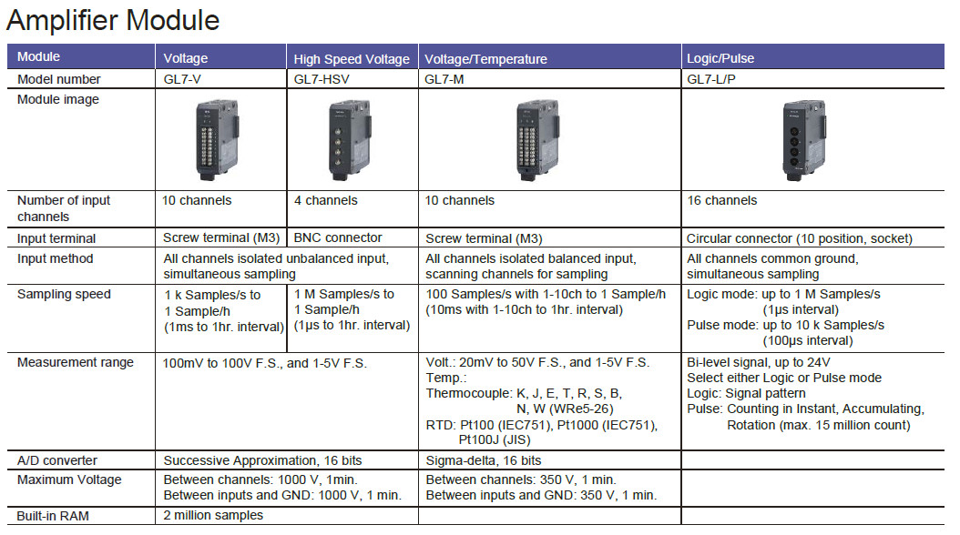
RAM (2 million samples, built-in Signal conditioning module), Flash memory (2 gigabytes, built-in the main module)
|
|
External *10
|
SD card (Support SDHC, up to 32 GB) slot, SSD (Approx. 64 GB)The file for capturing data is limited up to 2 GB.
|
|
Data saving function
|
Captured data *10
|
Built-in RAM, Built-in Flash, SD memory card, SSD (Data is saved directly to it.)
|
|
Data in built-in RAM
|
Specified number of data up 2 million samples increment of 1
|
|
Auto save *10
|
Available for the built-in RAM
Enabled (ON): Data in the RAM is saved automatically to the built-in Flash, SD memory card, SSD
Disabled (OFF): Data in the RAM is not maintained after power is turned off
|
|
Ring capturing mode *10 *11
|
Saves most recent data
Number of capturing data: 1000 to 2000000 points, Destination of data: Built-in RAM, Built-in Flash, SD memory card, SSD
|
|
During capturing data
|
Displaying information in two windows, Hot-swapping the SD memory card, Saving data in between cursors.
|
|
Backup *10
|
Backup interval: Off, 1, 2, 6, 12, 24 hrs.
Data destination: SD memory card, SSD, FTP server
|
|
Engineering Scale function
|
Measured value can be converted to the engineering unit
Analog voltage: Converts by four reference points (gain, offset)
Temperature: Converts by two reference points (offset)
Pulse count: Converts by two reference points (gain)
|
|
Synchronization between units
|
Start and Trigger *12
|
|
Accuracy of clock (at 23 degree Celsius)
|
+/- 0.002 % (Monthly deviation approx. 50 sec.)
|
|
Operating environment
|
0 to 45 ºC, 5 to 85 % RH (non condensed)
|
|
Power source
|
100 to 240 V AC, 50/60 Hz
|
|
Power consumption
|
Approx. 85 VA
|
|
Standard accessories
|
Quick guide, CD-ROM, AC power cable
|
|
External dimensions (W x D x H)
|
Main module: Approx. 193 x 141 x 160 mm (Excluding projectin), Alarm output terminal: Approx. 30 x 136 x 145 mm (Excluding projection)
|
|
Weight
|
Main module: Approx. 2 kg, Alarm output terminal: Approx. 350 g
|
Display module specifications
|
Model name
|
GL-Connection
|
|
Supported OS
|
Windows 7 (32/64-bits, Except Starter edition), Vista (32/64-bits), XP *13
|
|
Functions
|
Control GL7000, Real-time data capture, Replay data, Data format conversion
|
|
Controlled units
|
Up to 10 units (Max. 1120 channels)
|
|
GL7000 Settings control
|
Input settings, Memory settings, Trigger and Alarm settings, Other settings
|
|
Captured data *14
|
Built-in RAM (Binary format), Built-in Flash memory (Binary, CSV format), SD memory card (Binary, CSV format), SSD (Binary, CSV format)
The sampling is limited by the number of channels used. (1 ms per channel. When 10 channels are set, sampling is limited to 10 ms.)
|
|
Displayed information
|
Analog waveforms, Logic waveforms, Pulse waveforms, Digital values
|
|
Display mode
|
Y-T waveform with digital values, X-Y graph in real time, Cursor information, Capture condition, Alarm information
|
|
File operation
|
Converts binary data to the CSV data (specific period, all data in one file, multiple files), Creates a new file with compression or by consolidating multiple file.
|
|
Warning Function
|
Send e-mail to the specified address when the alarms occur
|
|
Statistical calculation
|
Capturing data: Maximum, Minimum, Peak or Average
Replaying data: Maximum, Minimum, Peak, Average or RMS in between cursors
|
|
Search function
|
Level
|
Specific level in any channel
|
|
Alarm
|
Occurred alarm in any channel
|
|
Time
|
Beginning, center, end of the data, Trigger point, Specific time (absolute, relative), Specific number
|
|
Operation lock
|
Operation screen can be locked (It is unlocked with the password.)
|
Display module specifications
|
Model name
|
GL7-DISP
|
|
Display device
|
5.7-inch TFT color LCD monitor (VGA: 640 x 480 dots)
|
|
Operation section
|
Touch panel and Cursor keys *15
|
|
Touch panel
|
Capacitive type touch panel, Operated by finger or the proprietary pen
|
|
Displayed language
|
English, French, German, Chinese, Korean, Japanese
|
|
Screen saver
|
Turns off backlight by 10, 30 sec., 1, 2, 5, 10, 30, 60 min.
|
|
Displayed information
|
Waveform in Y-T with digital values, Waveform only, Digital value, Waveform in X-Y
|
|
Connection cable
|
LAN cable (CAT5 class, Straight connection, Up to 10m) *16
|
|
Standard accessories
|
Bracket for slanted mount, Connection cable (40cm), Ground cable, Screws
|
|
External dimensions (W x D x H)
|
Approx. 187 x 35 x 199 mm (Excluding projection)
|
|
Weight
|
Approx. 530 g
|
SSD module specifications
|
Model name
|
GL7-SSD
|
|
Memory device
|
Solid state disk (SSD), Form factor: 2.5-inch HDD
|
|
Capacity
|
Approx. 64 GB (The file size of the captured data is limited up to 2 GB.)
|
|
Sampling speed *17
|
Attached 1 or 2 modules
|
Max. 1 M Samples/s
|
|
Attached 1 or 2 modules
|
Max. 500 k Samples/s
|
|
Attached 5 to 10 modules
|
Max. 200 k Samples/s
|
|
External dimensions (W x D x H)
|
Approx. 49 x 136 x 160 mm (Excluding projection)
|
|
Weight
|
Approx. 770 g
|
*1 Excluding the function module as the Display module or SSD module.
*2 The Input/Output cable (B-513) is required for connecting the signal. The Autobalance signal input and the Busy signal output are used in the DC Strain Module.
*3 The alarm signals are output on the terminal block attached to the main module as standard accessory.
*4 It is available on the Logic/Pulse module.
*5 Method of detection Volt./Temp. module: The alarm is detected in the sampling interval when the sampling interval is shorter than 5 seconds. The alarm is detected every 5 seconds when the sampling interval is longer than 5 seconds. Other modules: The alarm is detected in every 1ms when the sampling interval is shorter than 1ms. The alarm is detected in the sampling interval when the sampling interval is set between 2ms to 5 seconds. The alarm is detected every 5 seconds when the sampling interval is longer than 5 seconds.
*6 It is available when the captured data is saved to the built-in RAM. The pre-trigger function may not work in combination with the trigger settings.
*7 The result of real time calculation is displayed in the digital display mode.
*8 When the captured data destination is set to the built-in-RAM, the captured data is not maintained after a power failure occur. The built-in Flash or the SD memory card may be damaged by a power failure if it being accessed to writ data. If the memory device is not damaged, the closed data file is maintained. The file is closed every one minute while data is being captured.
*9 The USB drive mode is started by setting of the switch on the main module. It can be also started when the power is turned on while pressing the key on the display module.
*10 The SD memory card is included as the standard accessory. The SSD module is an option.
*11 The capacity for saving the data is set to one third of available memory when the captured data destination is set to a device other than the built-in-RAM. The sampling speed is limited up to 10 samples (100ms interval).
*12 The Sync cable (B559) is required when this function is used. The GL-Connection software is required when the synchronizing function is used.
*13 The SP2 or higher service pack need to be installed.
*14 The captured data that is saved to the built-in-RAM or SSD cannot be saved to the PC in real time. The data in built-in-RAM or SSD needs to be transferred to the PC after data captur is complete.
*15 Most operations can be selected by both touch panel and keys.
*16 When the display module is mounted at an angle using the bracket, the display module is connected to the main module by a LAN cable that is attached to the display module as standard accessory.
*17 The sampling speed in the GL7000 is limited to the fastest sampling speed of attached signal conditioning module. When the specified sampling speed is faster than the module, the sampling is done in fastest sampling on the module. The same value is stored to the memory device in the specified sampling speed until data is renewed by the next sampling.
Voltage/Temperature Module Specifications
|
Model number
|
GL7-M
|
|
Number of input channels
|
10 channels
|
|
Input method
|
All channels isolated balanced input, Scans channels for sampling, Screw terminal (M3 screw)
|
|
Sampling speed
|
100 Samples/s at 1-10ch to 1 Sample/h (10 ms with 1-10ch to 1 hr. interval)
|
|
Measurement range
|
Voltage
|
20, 50, 100, 200, 500 mV, 1, 2, 5, 10, 20, 50 V, and 1-5 V/F.S.
|
|
Temperature
|
Thermocouple: K, J, E, T, R, S, B, N, and W (WRe5-26),
RTD: Pt100, JPt100 (JIS), Pt1000 (IEC751)
|
|
Humidity *1
|
0 to 100 % (using scaling function in 5V range, humidity sensor B-530)
|
|
Measurement accuracy*2
|
Voltage
|
± 0.1 % of F.S.
|
|
Temperature
|
Thermocouple
|
Measurement range
|
Measurement accuracy
|
|
R/S
|
0 °C ≤ TS ≤ 100 °C
|
± 5.2 °C
|
|
100 °C < TS ≤ 300 °C
|
± 3.0 °C
|
|
R: 300 °C < TS ≤ 1600 °C
|
± (0.05 % of reading + 2.0 °C)
|
|
S: 300 °C < TS ≤ 1760 °C
|
± (0.05 % of reading + 2.0 °C)
|
|
B
|
400 °C ≤ TS ≤ 600 °C
|
± 3.5 °C
|
|
600 °C < TS ≤ 1820 °C
|
± (0.05 % of reading + 2.0 °C)
|
|
K
|
-200 °C ≤ TS ≤ -100 °C
|
± (0.05 % of reading + 2.0 °C)
|
|
-100 °C < TS ≤ 1370 °C
|
± (0.05 % of reading + 1.0 °C)
|
|
E
|
-200 °C ≤ TS ≤ -100 °C
|
± (0.05 % of reading + 2.0 °C)
|
|
-100 °C < TS ≤ 800 °C
|
± (0.05 % of reading + 1.0 °C)
|
|
T
|
-200 °C ≤ TS ≤ -100 °C
|
± (0.1 % of reading + 1.5 °C)
|
|
-100 °C < TS ≤ 400 °C
|
± (0.1 % of reading + 0.5 °C)
|
|
J
|
-200 °C ≤ TS ≤ -100 °C
|
± 2.7 °C
|
|
-100 °C < TS ≤ 100 °C
|
± 1.7 °C
|
|
100 °C < TS ≤ 1100 °C
|
± (0.05 % of reading + 1.0 °C)
|
|
N
|
0 °C ≤ TS ≤ 1300 °C
|
± (0.1 % of reading + 1.0 °C)
|
|
W
|
0 °C ≤ TS ≤ 2000 °C
|
± (0.1 % of reading + 1.5 °C)
|
|
Reference Junction Compensation (R.J.C.) accuracy: ± 0.5 °C *3
|
|
RTD
|
Measurement range
|
Driving current
|
Accuracy
|
|
Pt100
|
-200 °C to 850 °C (FS = 1050 °C)
|
1 mA
|
± 1.0 °C
|
|
JPt100
|
-200 °C to 500 °C (FS = 700 °C)
|
1 mA
|
± 0.8 °C
|
|
Pt1000
|
-200 °C to 500 °C (FS = 700 °C)
|
0.2 mA
|
± 0.8 °C
|
|
R.J. Compensation
|
Selecting of the internal or external
|
|
A/D Converter
|
Sigma-Delta type, 16 bits (effective resolution: 1/40000 of measuring full range)
|
|
Stability with temperature
|
Gain
|
0.01 % of F.S./°C
|
|
Zero *4
|
0.02 % of F.S./°C
|
|
Input impedance
|
1 MΩ ± 5 %
|
|
Maximum input voltage
|
Between (+) / (-) terminal
|
60 V p-p
|
|
Between channels
|
60 V p-p
|
|
Between channel / GND
|
60 V p-p
|
|
Maximum voltage
|
Between channels
|
350 V p-p (1 minute)
|
|
Between channel / GND
|
350 V p-p (1 minute)
|
|
Isolation
|
Between input / GND
|
Min. 50 MΩ (at 500 V DC)
|
|
Common-mode rejection ratio
|
Min. 90 dB (50/60 Hz, Signal source impedance: Max. 300 Ω)
|
|
Filter
|
Off, 2, 5, 10, 20, 40 (Moving average in selected number. When the sample is longer than 5 seconds, the data sampled in the sub-sample (5 seconds) will be used for creating the average value. )
|
|
5V output
|
Driving the humidity sensor B-530, 1 channel
|
|
External dimensions (W×D×H)
|
49 x 136 x 160 mm (Excluding projection)
|
|
Weight
|
Approx. 770 g
|
Voltage module specifications
|
Voltage module specifications
|
Voltage
|
High Speed Voltage
|
|---|
|
Model number
|
GL7-V
|
GL7-HSV
|
|
Number of input channels
|
10 channels
|
4 channels
|
|
Input method
|
All channels isolated unbalanced input, Simultaneous sampling, Screw terminal
|
All channels isolated unbalanced input, Simultaneous sampling, BNC connector
|
|
Sampling speed (interval)
|
1 k Samples/s to 1 Sample/h (1ms to 1h)
|
1 M Samples/s to 1 Sample/h (1μs to 1h)
|
|
Measurement range
|
100, 200, 500 mV,1, 2, 5, 10, 20, 50, 100 V, and 1-5 V/F.S.
|
|
Measurement accuracy*5
|
± 0.25 % of F.S.
|
|
A/D Converter
|
Successive Approximation type, 16 bits (effective resolution: 1/40000 of measuring full range)
|
|
Stability with temperature
|
Gain
|
0.01 % of F.S./°C
|
|
Zero
|
0.02 % of F.S./°C
|
|
Input impedance
|
1 MΩ ± 5 %
|
|
Maximum input voltage
|
Between (+) / (-) terminal
|
100mV to 1V range: 60 V p-p, 2V to 100V range: 100 V p-p
|
|
Between channels
|
60 V p-p
|
|
Between channel / GND
|
60 V p-p
|
|
Maximum voltage
|
Between channels
|
1000 V p-p (1 minute)
|
|
Between channel / GND
|
1000 V p-p (1 minute)
|
|
Isolation
|
Between input / GND
|
Min. 50 MΩ (at 500 V DC)
|
|
Common-mode rejection ratio
|
Min. 90 dB (50/60 Hz, Signal source impedance: Max. 300 Ω)
|
|
Frequency response
|
DC to 1 k Hz (at +1/-3 dB)
|
DC to 2 k Hz (at +1/-3 dB)
|
|
Filter (Low pass)
|
Off, Line(1.5Hz), 5, 50, 500 Hz (-3dB, 6dB/oct)
|
Off, Line(1.5Hz), 5, 50, 500, 5k, 50k Hz (at -3dB, 6dB/oct)
|
|
External dimensions (W×D×H)
|
49 x 136 x 160 mm (Excluding projection)
|
|
Weight
|
Approx. 840 g
|
Approx. 740 g
|
Logic/Pulse Module Specifications
|
Model number
|
GL7-L/P
|
|
Number of input channels
|
16 channels
|
|
Input method
|
All channels common ground, simultaneous sampling, Circular connector (4ch/connector)
|
|
Sampling speed
|
Logic mode
|
Up to 1 M Samples/s (1μs interval)
|
|
Pulse mode
|
Up to 10 k Samples/s (100μs interval)
|
|
Measurement mode
|
Selecting of the Logic input mode or Pulse input mode *6
|
|
Mode
|
Pulse
|
Rotation count (RPM), Accumulating count, Instant count
|
|
Rotation count (RPM)
|
Function
|
Counting the number of pulses per sampling interval and then it is converted to RPM
|
|
Range
|
50, 500, 5000, 50 k, 500 k, 5 M, 50 M, 500 M rpm/F.S.
|
|
Accumulating count
|
Function
|
Accumulating the number of pulses from the start of measurement
|
|
Range
|
50, 500, 5 k, 50 k, 500 k, 5 M, 50 M, 500 M counts/F.S.
|
|
Instant count
|
Function
|
Counting the number of pulses per sampling interval (count is reset at each sampling)
|
|
Range
|
50, 500, 5 k, 50 k, 500 k, 5 M, 50 M, 500 M counts/F.S.
|
|
Max. input frequency
|
1 M Hz
|
|
Max. number of count
|
15 M counts (24 bits counter is used)
|
|
Input signal
|
Voltage range
|
0 to +24 V (common ground)
|
|
Signal type
|
Contact (Relay), Open collector, Voltage
|
|
Threshold
|
Approx. 2.5 V
|
|
Hysteresis
|
Approx. 0.5 V (2.5 V to 3 V)
|
|
Filter
|
Off or On (-3 dB at 50 Hz)
|
|
External dimensions (W×D×H)
|
49 x 136 x 160 mm (Excluding projection)
|
|
Weight
|
Approx. 700 g
|
*1 Using optional humidity sensor (B-530).
*2 Subject to the following conditions;
- Room Temperature is 23°C ±5°C
- When 30 minutes or more have elapsed after power was turned on.
- Filter is set to 10.
- Sampling rate is set to 1s with 10 channels.
- GND terminal is connected to ground.
*3 Wire size of thermocouple to use is 0.32mm in T type, 0.65mm in other type.
*4 It is effective when the 10, 20, 50ms sampling is used. When the sampling is slower than 100ms, it is not effective by executing the Zero calibration periodically.
*5 Subject to the following conditions;
- Room Temperature is 23°C ±5°C.
- When 30 minutes or more have elapsed after power was turned on.
- Filter is set to Line (1.5 Hz).
- Sampling rate is set to 1s.
- GND terminal is connected to ground
*6 The measuring mode is set in each module (16 channels). When the module is used in the Logic, up to 7 modules can be attached to one main module. (max. 112 ch) When the module is used in the Pulse, up to 2 modules can be attached to one main module. (max. 32 ch) The amplifier module can be attached to up to 10 modules. The maximum number of channels is limited to up to 112 channels.
|
Product Reviews
|
|