| | |
|
| |
| | |
|


|
Amprobe AT-7020 Advanced Wire Tracer Kit
|
Item Number: AT-7020
Manufacturer: Amprobe
Part Number: AT-7020
* Whole number only
|
|
Amprobe AT-7020 Advanced Wire Tracer Kit
The AT-7020 presents the AT-700-R Receiver which has a protected Smart Sensor feature. This allows for instant display of the location and orientation of energized wires in walls, floors, and ceilings. The Tip Sensor is developed to trace wires in challenging areas such as, corners, tight spaces and junction boxes.
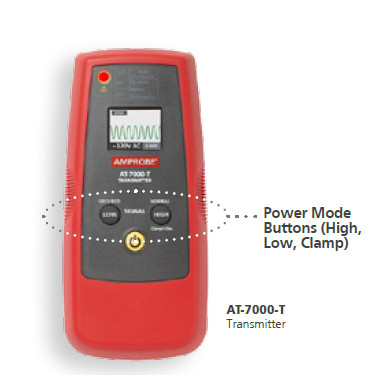
The Kit also offers the AT-7000-T Transmitter which has two, automatically-selected frequency modes for ideal tracing on energized and de-energized circuits, as well as three power modes (high, low, clamp) for numerous environments.
Features
- Locates and traces energized and de-energized wires and breakers in floors, walls, and ceilings
- Pinpoints shorts and opens
- Traces AC/DC Circuits from 0-600 V
- Features three power modes
- "High" power mode for normal circuits
- "Low" power mode for precision tracing in difficult areas
- Clamp power mode provides a boosted induction signal via the optional signal clamp
- Offers two output frequency modes for optimal tracing
- 6 kHz for energized circuits
- 33 kHz for de-energized circuits
- Provides embedded help screens to simplify setup
- Comes with custom Amprobe hard carrying case, test leads, and accessories
- Compatible with optional Signal Booster Rechargeable Battery Pack (BR-7000-T), Signal Clamp (SC-7000) clamp-on attachment, and TIC 410A Hot Stick attachment to extend your reach
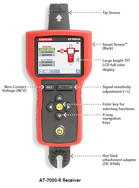
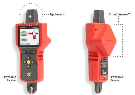
Tip Sensor
The shape of the tip sensor allows tracing in
hard to reach areas, corners & tight spaces,
as well as precise circuit breaker and fuse
identification. By utilizing two different types of
antennas (inductive coil and capacitive), the tip
sensor enables optimal tracing results of both
energized and de-energized circuits, which are
automatically selected by operating mode. |
Smart Sensor™
Quickly and easily determine the precise
direction and location of energized wires in
walls, floors and ceilings with the patented
Smart Sensor™. Combined with a fast signal
processor that measures small changes in the
detected signal multiple times per second, this
new technology provides unmatched precision
and ease of use for tracing energized wires. |
 |
 |
AT-7000-T Transmitter
Featuring three power modes “high”, “low”,
and “clamp” and two output frequencies (6kHz
and 33 kHz), the AT-7000-T incorporates the
best technologies available for optimal wire
tracing and breaker identification on both
energized and de-energized circuits. The AT-
7000-T automatically sets the frequency based
on detected voltage, and prompts the user to
set the power level based on their application.
The color TFT LCD screen displays the detected
voltage, frequency output and power mode. |
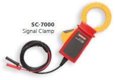
Signal Clamp
When there’s no access to bare conductors, use
the SC-7000 signal clamp to induce a signal into
either energized or de-energized circuits for
wire tracing and load locating. The AT-7000-T
transmitter’s “clamp” mode provides a boosted 6
kHz signal through the clamp to further improve
accuracy and performance.
|
Technical Specifications
| Traces energized and de-energized wires |
• |
• |
| Locates energized and de-energized breakers |
• |
• |
| Pinpoints opens and shorts |
• |
• |
| Traces AC/DC circuits 0-600 V |
• |
• |
| Three power modes |
• |
• |
| Two frequency modes for optimal tracing |
• |
• |
| Signal Booster Rechargeable Battery Pack (BR-7000-T) |
optional |
• |
| Signal Clamp (SC-7000) |
optional |
• |
| AT-7000-R Receiver |
• |
• |
| AT-7000-T Transmitter |
• |
• |
| TL-7000 Test Leads |
• |
• |
| CC-7000 Hard Carrying Case |
• |
• |
| SC-7000 Signal Clamp |
optional |
• |
| HS-1 Hanger |
optional |
• |
| BR-7000-T Booster Battery |
optional |
• |
| BR-7000C Battery Charger |
optional |
optional |
| User Manual |
• |
• |
|
|
|
|
Description
- TL-7000 Test Leads: Test lead set with alligator clips (black and red), 30 ft. grounding lead, power cord, plug adaptors and light socket adapter
- CC-7000 Carrying Case: Custom Amprobe hard carrying case that securely holds transmitter, receiver, signal clamp, test leads and accessories
- SC-7000 Signal Clamp: Signal clamp accessory for inducing a signal into wires without access to bare conductors
- HS-1 Hanger: Three-way magnetic hanger for AT-7000-T transmitter, allowing for convenient hanging of unit, placement on belt or as a stand
- BR-7000-T Booster Battery: Signal booster rechargeable battery pack (LI-ION, 7.2 V, 2.2 Ah), provides increased signal transmission power in High and Clamp modes
- BR-7000C Battery Charger: External battery charger for BR-7000-T
|
Specifications
|
AT-7000-R Receiver
|
AT-7000-T Transmitter
|
SC-7000 Signal Clamp
|
|
TFT LCD Color Display size
|
3.5 in (8.89 cm)
|
1.77 in (4.5 cm)
|
–
|
|
TFT LCD Color Display Dimensions
|
2.76 x 2.07 in (7.01 x 5.26 cm)
|
1.1 x 1.38 in (2.79 x 3.51 cm)
|
–
|
|
TFT LCD Color Display Resolution
|
320px x 240px
|
128px x 160px
|
–
|
|
TFT LCD Color Display type
|
TFT LCD
|
RGB x TFT
|
–
|
|
TFT LCD Color Display
|
•
|
•
|
–
|
|
Backlight
|
•
|
•
|
–
|
|
mDDR
|
64 MB
|
64 MB
|
–
|
|
FLASH memory
|
128 MB
|
128 MB
|
–
|
|
Audio
|
95 dB
|
–
|
–
|
|
Operating Temperature range
|
0 to 120˚F (-17.77 ˚C to 49˚C)
|
0 to 120˚F (-17.77˚C to 49˚C)
|
0 to 120˚F (-17.77˚C to 49˚C)
|
|
Storage Temperature
|
-40 to 150˚F (-40 to 65.5˚C)
|
-40 to 150˚F (-40 to 65.5˚C)
|
-40 to 150˚F (-40 to 65.5˚C)
|
|
Operating Humidity
|
95% R.H max
|
95% R.H max
|
95% R.H max
|
|
Operating altitude
|
2000 m
|
2000 m
|
2000 m
|
|
Measurement Category
|
CAT IV 600 V
|
CAT IV 300 V
|
CAT IV 600 V
|
|
Transient protection
|
–
|
8.00 kV (1.2/50 uS surge)
|
–
|
|
Pollution degree
|
2
|
2
|
2
|
|
Drop test
|
3.28 ft (1 m)
|
3.28 ft (1 m)
|
3.28 ft (1 m)
|
|
Power Supply
|
4xAA Alkaline battery
|
90-270 V AC/DC, 40-400 Hz
AT-7030: BR-7000-T: LI-ION, 7.2 V, 2.2 Ah
AT-7020: 6x AA Alkaline Battery
|
–
|
|
Power consumption
|
4xAA battery: 2W
|
AT-7030: BR-7000-T battery: 2W
AT-7020: 6xAA battery:2W
AC line voltage (Charging state): 10W AC line voltage: 3W
|
–
|
|
Charging voltage (BR-7000-T)
|
–
|
85-270 V
|
–
|
|
Charging duration (BR-7000-T)
|
–
|
16 h
|
–
|
|
Power up time
|
30 s
|
20 s
|
–
|
|
Non-Rechargeable Battery lifetime
|
9 h
|
9 h
|
–
|
|
Rechargeable Battery lifetime
(BR-7000-T)
|
–
|
10 h
|
–
|
|
Leakage current (non-rechargeable)
|
1.1 to 2.6 uA
|
6 to 14 uA
|
–
|
|
Leakage current (rechargeable)
|
–
|
1.2 to 4 uA
|
–
|
|
IP Rating
|
IP52
|
IP40
|
–
|
|
Sampling rate
|
6.25 kHz Signal: 62.5 kSPS
32.768 kHz: 256 kSPS
NCV: 62.5 kSPS
|
62.5 kSPS
|
–
|
|
Signal Response
|
Audible beep, bargraph display,
numeric display
|
Numeric display
|
–
|
|
Response time
|
Smart mode: 750 ms
Tip Sensor Energized: 300 ms Tip Sensor De-Energized: 750 ms NCV: 500 ms, Battery monitoring: 5 s
|
Voltage measurement: 1.5 s
Battery monitoring: 5 s
|
Instantaneous
|
|
Voltage Measurement
|
–
|
9-300 V, DC to 400 Hz
|
–
|
|
Non-Contact Voltage (NCV)
|
90-600 V AC
|
–
|
–
|
|
LED Indicator
|
Green Flashing: Signal Detection
|
Red: Energized OFF: De-Energized Orange: Over voltage
|
–
|
|
Operating Frequency
|
Energized: 6.25 kHz
De-Energized: 32.768 kHz
|
Voltage measurement: 40-400 Hz
Energized: 6.25 kHz
De-Energized: 32.768 kHz
|
Energized: 6.25 kHz
De-Energized: 32.768 kHz
|
|
Acoustic Indication
|
1 kHz Piezo Buzzer
|
–
|
–
|
|
Range Detection (Open air)
|
–
|
–
|
–
|
|
Smart mode
|
Pinpointing: Around 1.97 in (5 cm) radius
Direction indication: Up to 5 ft (152.4 cm)
|
–
|
–
|
|
TIP Sensor: Energized
|
Pinpointing: Around 1.97 in (5 cm)
Detection: Up to 22 ft (670.56 cm)
|
–
|
–
|
|
TIP Sensor: De-Energized
|
Pinpointing: Around 1.97 in (5 cm) radius
Detection: Up to 14 ft (426.72 cm)
|
–
|
–
|
|
NCV
|
Detection: Up to 4 ft (121.92 cm)
|
–
|
–
|
|
Current Output (Low) Energized
|
–
|
53 mA rms
|
–
|
|
Current Output (High) Energized
|
–
|
92 mA rms
|
–
|
|
Current output (Low)
with BR-7000-T Energized
|
–
|
53 mA rms
|
–
|
|
Current output (High)
with BR-7000-T Energized
|
–
|
120 mA rms
|
–
|
|
Voltage output (Low) De-Energized
|
–
|
60 Vp-p
|
–
|
|
Voltage output (High) De-Energized
|
–
|
120 Vp-p
|
–
|
|
Voltage output (Clamp) De-Energized
|
–
|
180 Vp-p
|
–
|
|
Jaw Opening
|
–
|
–
|
2 in (5.08 cm)
|
|
Fuse
|
–
|
3.15A, 600V MAX, SLOW 5X20MM
|
–
|
|
Dimensions
|
10.92 x 4.43 x 2.55 in
(27.75 x 11.25 x 6.483 cm)
|
8.5 x 4 x 2.2 in
(21.59 x 10.16 x 5.59 cm)
|
8.2 x 3.2 x 1.68 in
(20.83 x 8.13 x 4.27 cm)
|
|
Weight
|
1.20 lb (0.544 kg)
|
1.30 lbs (0.593 kg)
|
0.648 lb (0.294 kg)
|
|

The Amprobe HS-1 is a three-way magnetic hanger for AT-7000-T transmitter, allowing for convenient hanging of unit, placement on belt or as a stand.
|

The Amprobe TL-7000 Test Lead Set come with alligator clips (black & red), 30 ft. grounding lead, power cord, plug adapters and light socket adapter.
|

The Amprobe BR-7000C is an external battery charger for BR-7000-T.
|

The Amprobe BR-7000-T Signal booster rechargeable battery pack (LI-ION, 7.2 V, 2.2 Ah), provides increased signal transmission power in High and Clamp modes.
|

The Amprobe CC-7000 is a custom Amprobe hard carrying case that securely holds transmitter, receiver, signal clamp, test leads and accessories.
|

The Amprobe SC-7000 Signal clamp accessory is used to induce a signal into wires without access to bare conductors.
|

The Amprobe AT-7030 kit can traces wires in walls, ceilings, floors and corners, locate breakers and fuses, and pinpoint shorts and opens.
| |
Product Reviews
|
|